Installation Instructions for Auto-Draft® Rooftop Inducer CHIMNEY FANS RH75H0 AND RH1500H
August 28, 2023
Note: This is an overview of installation procedure. Please consult the manual shipped with your fan for complete installation and safety information.
For non-condensing applications only. Not suitable for Side Wall terminations.
Important: Use of this product could cause flues to reverse (back-draft) on other heating equipment within the same structure if adequate make-up air is not provided. Check for flue gas spillage of atmospherically vented heaters after rooftop inducer installation and always have working carbon monoxide detectors installed per the CO detector manufacturer's instructions and local codes. Make-up/combustion air fans are available from Rockford if necessary.
WARNING
These instructions are intended as an aid to qualified, licensed service personnel for proper installation, adjustment and operation of this unit. Read these instructions thoroughly before attempting installation or operation. Failure to follow these instructions may result in improper installation, adjustment, service or maintenance possibly resulting in fire, electrical shock, carbon monoxide poisoning, explosions, personal injury or property damage. This installation manual does not contain any system documentation.
DIMENSIONS AND SPECIFICATIONS

WARNING
Failure to install, maintain and/or operate the Rooftop Inducer in accordance with manufacturer's instructions may result in conditions which can produce bodily injury and property damage.
WARNING
The Rooftop Inducer must be installed by a qualified installer in accordance with these instructions and all local codes or in their absence in accordance with the latest edition of The National Fuel Gas Code (NFPA 54), NFPA 211 or 31 when applicable, the latest edition of the National Electrical Code (NFPA 70) and the Occupational Safety and Health Act (OSHA) when applicable. In the absence of local codes in Canada, installations must comply with the Canadian Electrical Code (CSA Std 22.1 ), the latest edition of the Natural Gas Installation Code (CAN/CGA-B149.1), the Propane Installation Code (CAN/CGA-B149.2) and the Installation Code for Oil Burning Equipment (CSA Std B139-M91).
Improper installation can create a hazardous condition such as an explosion, fire, electrical shock or carbon monoxide poisoning resulting in property damage, personal injury or death.
INSTALLER CAUTIONS
WARNING
Disconnect the power supply when making wiring connections or when working around the Inducer impeller and motor. Failure to do so can result in electrical shock, personal injury, death or property damage.
INSTALLATION OF ROOFTOP INDUCER
WARNING
The Rooftop motor side is heavy. Remove (2) hinge pins and (2) latch screws opposite hinge side to separate the motor section from the mounting base prior to installation. When removing the motor side, use extreme caution so internal parts such as the impeller are not damaged.
Make sure vent pipe is adequately installed and supported for weight of inducer. Optional RT-Series rooftop stands or a frame to support weight of inducer may be necessary. The vent extending above the roofline may be shortened for a more stable and aesthetic installation since the Rooftop Inducer provides draft regardless of chimney height.
IMPORTANT: Disconnect the power supply when making wiring connections or when working around the fan impeller and motor. Failure to do so can result in electrical shock, personal injury, death or property damage.
INDUCER BASE INSTALLATION
All models include mounting kits to securely attach the Inducer Base to any type of insulated or single wall metal pipe or tile lined flue.

MOUNTING INDUCER BASE ON METAL VENT PIPE
NOTE: Discard adapter plate, finger clamps and 3 1/2" bolts if mounting on metal vent pipe.

A Mounting Plate and Inlet Collar is included with each Rooftop Inducer. The RT750 Series collar will slip inside any metal pipe as small as 8" diameter ID and as large as 12" OD. The RT1500 Series collar will slip inside any metal pipe as small as 12" ID and as large as 20" OD. If your application has a metal pipe smaller than the noted diameters use an increaser appropriate for pipe type to transition to minimum diameter noted.
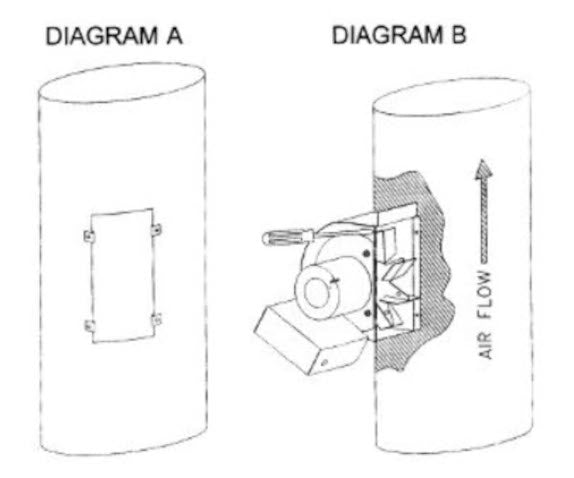
- Insert Inlet Collar through Mounting Plate. Place Inducer Base on top of Inlet Collar and Mounting Plate to sandwich Inlet Collar flange between them. Insert (4) 1/2" 10-32 carriage bolts through Mounting Plate and Inducer Base and tighten (4) 10-32 lock nuts on top of Inducer Base. Secure (4) Pipe Straps to the holes on the sides of the Inducer Base with included (4) 3/8" 8-32 screws and lock nuts, (See Diagram A)
- IMPORTANT: Before inserting Inlet Collar / Inducer Base assembly into vent pipe note that the electrical connection is on the hinged side of the Inducer. Make sure that the Inducer Base is positioned so that Inducer swings towards the desired direction. Using RTV or equivalent high temperature silicone apply a generous bead to the top edge of the metal vent pipe. Insert Inlet Collar / Inducer Base assembly into vent pipe considering hinge location. lnsert the large adjustable pipe clamp through the loops of the pipe straps and tighten pipe clamp until it snugly grips the OD of the vent. NOTE: RT1500 Series will have to use both pipe clamps provided. (See Diagram B).
MOUNTING INDUCER BASE ON CLAY TILE FLUE LINERS
NOTE: Discard mounting plate, pipe straps and pipe clamps if mounting on a tile flue liner.
1. Flip the Inducer Base bottom side up and position finger clamps in each corner. Place washer on (4) 3 1/2" adjustment bolts and insert through holes in corners and thread into finger clamp. Insert (4) 1/2" 10-32 carriage bolts through slots in finger clamps and through Inducer Base holes. Loosely secure on top side of Inducer Base with included (4) 10-32 lock nuts, (See Diagram C).
2. Place a generous bead of RTV or equivalent high temperature silicone on top of tile liner, (See Diagram D). Position the Inducer Base on top of the chimney liner, inserting the finger clamps into the liner interior. IMPORTANT: Note location of hinges to make sure that the Inducer Base is positioned so that Inducer swings towards the desired direction. The electrical whip is located on the hinged side. Once positioned in center of flue, pull the head of each 3 1/2" adjustment bolts out until the finger clamps make contact with the interior wall of the liner. Tighten opposite corners until finger clamps firmly secure the Inducer Base to the liner interior. CAUTION: Over-tightening could crack tile liner, (See Diagram E).

3. When finger clamps are firmly tightened, tighten down finger clamp 10-32 lock nuts on top of Inducer Base, (See Diagram F).
4. Place Adapter Plate on Inducer Base and mark Adapter Plate underside with a marker by tracing the interior of chimney. CAUTION: Sharp edges-wear gloves. lf underside cannot be easily marked take measurements of chimney to determine Adapter Plate opening. (See Diagram G.)
5. If Adapter Plate can't be easily marked by tracing interior of chimney, mark center lines on Adapter Plate and use chimney opening measurements to mark the Adapter Plate to cut out chimney opening, (See Diagram H).

6. Fill any gaps on exterior of chimney flue and Inducer Base with RTV or equivalent high temperature silicone, (See Diagram I).
7. Use a tin snips or equivalent to cut marks made on Adapter Plate to expose inside of tile liner. Confirm Adapter Plate opening exposes full chimney opening. Place a thin bead of RTV or equivalent high temperature silicone around Adapter Plate opening and place silicone side down on Inducer Base, (See Diagram J).

ROOFTOP INDUCER MOUNTING AND SCISSOR
Set the Inducer top motor side on top of the Inducer Base, aligning the hinges. Insert the two hinge pins with the heads on the outside portion of the hinges, (See Diagram K).
Install hinges as follows: Inducer Top hinge: Insert 1/2" threaded stud through Inducer top, (2) washers, hinge (with stop on outside), spacer, washer and 10-32 lock nut. Inducer Base hinge: Insert 1/2" threaded stud through Inducer Base, washer, hinge (with stop outside), spacer, (2) washers and 10-32 lock nut, (See Diagram L). Use (2) provided 3/8" 8-32 self tapping screws to secure Inducer top to Inducer Base through the two oval brackets on front of Inducer.
Insert Discharge Grilles on both sides with (3) 3/8" 8-32 self tapping screws provided, (See Diagram M).
INSTALLING ELECTRICAL WHIP
Remove the (2) 8-32 nuts holding coverplate and gasket on the electrical access of the Inducer. Pull the wires out of the lnducer and wire nut them to the electrical leads from the whip referencing appropriate diagram below. Carefully stuff the wired connections back into the Inducer and secure coverplate and gasket to Inducer housing using the nuts removed from above. Firmly tighten until gasket compresses, (See Diagram Q).Secure box on opposite end of whip to power supply conduit and wire in accordance to the diagram appropriate for installation. Place provided gasket between cover and box firmly tighten.
WARNING
All wiring from the Rooftop Inducer to the appliance must be in compliance with local codes or in their absence, the National Electric Code (NFPA 70).
All wiring from the Rooftop Inducer to the appliance must be appropriate class 1 wiring as follows: Installed in rigid metal conduit, intermediate metal conduit, rigid non-metallic conduit, electrical metallic tubing, Type MI Cable or be otherwise suitably protected from physical damage.

MODEL RT750H / RT1500H SPEED CONTROL ADJUSTMENT
Model RT750H and RT15OOH include a motor speed control. Do not alter the internal pot or use a different motor speed control. Do not wire so that speed control varies the motor cooling fan speed. Always have the inducer operating prior to and during the entire burn cycle of a solid fuel stove or fireplace.
SPEED CONTROL INSTALLATION
1. install the speed control in an indoor location adjacent to the solid fuel stove or fireplace, ideally where the flames and smoke can be viewed when speed adjustments are made.
2. The speed control requires a 2"x4" electrical box. 14-3 w/ground electrical wire is recommended because it consists of a white (neutral), Black (constant hot), Red (switched variable through speed control) and Green (ground) leads. Commercial applications may require 12 gauge wire and electrical disconnect on roof.
3. After speed control is installed and wired per Option 2 on Page 8, install included faceplate to junction box and push adjustment knob onto shaft of speed control.
4. Verify that Rooftop inducer activates when speed control is switched on and that Inducer performance decreases when knob is turned fully clockwise. This can be done by holding a candle in the unlit fireplace or stove near the flue outlet and observing flame and smoke.
Note: This is an overview of installation procedure. Please consult the manual shipped with your fan for complete installation and safety information.
Related Articles

DIY Center
(AKA ‘The Rockford Files’)
From video tutorials to product walkthroughs, we have a variety of DIY resources just for you! Click the button below to view our entire library.
Our 316Ti flexible chimney liner and chimney liner components have passed the rigorous testing at the Underwriters Laboratories with best in class status and are UL Listed. So if you are looking for UL listed chimney liner sold directly to homeowners, then look no further than Rockford Chimney